
CNC Hole Design Guide: Countersink Holes, Hole Spacing, and Key Design Considerations
Holes are one of the most common features in CNC machined parts and play a critical role in assembly, fastening, and component alignment. However, proper hole design requires more than simply selecting a diameter. Factors such as hole type, countersink dimensions, spacing between holes, and distance from part edges can directly affect part strength, machining accuracy, and manufacturing efficiency.
Countersink holes are widely used to allow flat-head screws to sit flush with or below a part surface, while proper hole spacing helps maintain structural integrity and avoid machining issues. For CNC machined components, engineers need to consider both functional requirements and manufacturing limitations when defining hole features in their designs.
This guide explains the fundamentals of countersink hole design, the differences between countersinks and counterbores, recommended hole spacing practices, and key considerations for creating CNC-ready part designs. By understanding these principles, designers can improve assembly performance, reduce manufacturing challenges, and create more reliable machined components.
What Is a Countersink Hole?
A countersink hole is a type of hole feature designed to allow a flat-head screw or fastener to sit flush with or below the surface of a part. It is created by adding a conical recess around the opening of a standard drilled hole, matching the angled shape of the fastener head.
Unlike a regular hole, a countersink hole includes an additional tapered section that provides space for the screw head. This prevents the fastener from protruding above the surface, creating a smoother profile and reducing interference with other components.
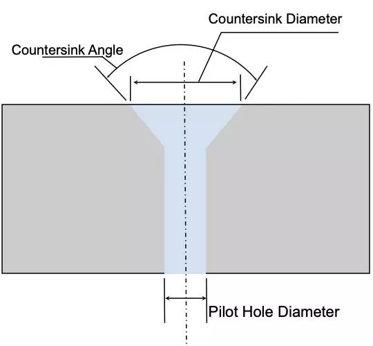
A countersink hole typically consists of several key dimensions:
- Pilot hole diameter: The main hole that accommodates the screw shaft or threaded section.
- Countersink diameter: The outer diameter of the conical recess that supports the screw head.
- Countersink angle: The included angle of the tapered opening, which must match the fastener head geometry.
- Countersink depth: The distance required for the screw head to sit at the desired position.
Countersink holes are commonly used in manufactured components that require mechanical fastening, including CNC machined parts, sheet metal components, aerospace structures, electronic housings, and precision assemblies.
When designing parts for manufacturing, countersink dimensions should be defined based on the selected fastener specifications and the functional requirements of the assembly.
Why Use Countersink Holes in Part Design?
Countersink holes provide several advantages in mechanical design by improving fastening performance, component integration, and overall product appearance.
Create a Flush Surface
The primary purpose of a countersink hole is to allow the screw head to sit level with the surrounding surface. This eliminates protruding fasteners and creates a smoother surface profile.
A flush surface is important in applications where external clearance, appearance, or contact between components matters, such as:
- Aerospace panels
- Electronic enclosures
- Machine covers
- Precision assemblies
Prevent Interference Between Components
Protruding screw heads can interfere with mating parts, moving components, or nearby structures. Countersink holes provide a recessed fastening solution that helps maintain proper fit and clearance between assembled components.
Improve Assembly Consistency
A properly designed countersink ensures that fasteners are positioned correctly and seated evenly. This improves assembly repeatability and helps maintain consistent clamping conditions across multiple fastening points.
Improve Part Appearance
In addition to functional benefits, countersunk fasteners create a cleaner and more finished appearance by hiding screw heads below the surface. This makes countersink holes suitable for products where both performance and visual quality are important.
Countersink Hole Dimensions and Design Requirements
Properly defining countersink dimensions is essential to ensure that fasteners fit correctly and that the part maintains its required strength and functionality. A countersink should not be designed only based on appearance; the dimensions need to match the fastener specifications, material thickness, and assembly requirements.
The main design factors for a countersink hole include the countersink angle, diameter, and depth.
Countersink Angle
The countersink angle refers to the included angle of the conical recess and must match the angle of the fastener head. Using an incorrect angle can prevent the screw from seating properly, causing uneven contact or improper assembly.
Common countersink angles include:
| Countersink Angle | Common Applications |
| 82° | Common for inch-standard flat-head screws |
| 90° | Widely used for metric fasteners and general applications |
| 100° | Commonly used in aerospace applications |
When specifying countersink features on engineering drawings, the angle should always be clearly defined to avoid confusion during manufacturing.
Countersink Diameter
The countersink diameter determines how much space is available for the fastener head. It should be large enough for the screw head to seat properly but not oversized, as an excessive diameter can weaken the surrounding material.
Factors affecting countersink diameter include:
- Screw head diameter
- Required flushness of the fastener
- Material thickness
- Structural requirements of the part
For precision components, the countersink diameter should be controlled carefully to ensure consistent fastener positioning during assembly.
Countersink Depth
Countersink depth determines how far the fastener head sits below or within the part surface. The correct depth depends on the screw head geometry and the desired surface condition.
An incorrect countersink depth may cause:
- Insufficient depth: The screw head remains above the surface and creates interference.
- Excessive depth: The recessed area removes unnecessary material and may reduce part strength.
When designing thin components, engineers should pay particular attention to countersink depth because removing too much material can affect the remaining wall thickness and structural performance.
Countersink Design Considerations for Manufacturing
Although countersink geometry is mainly determined by fastener requirements, manufacturing factors should also be considered during the design stage.
Important considerations include:
- Selecting standard fastener sizes whenever possible
- Providing complete hole specifications on drawings
- Ensuring sufficient material thickness around the countersink
- Considering tool access and inspection requirements
For CNC machined parts and other precision-manufactured components, clear design specifications help manufacturers select suitable tools and processes while maintaining consistent hole quality.
Countersink vs Counterbore: What Is the Difference?
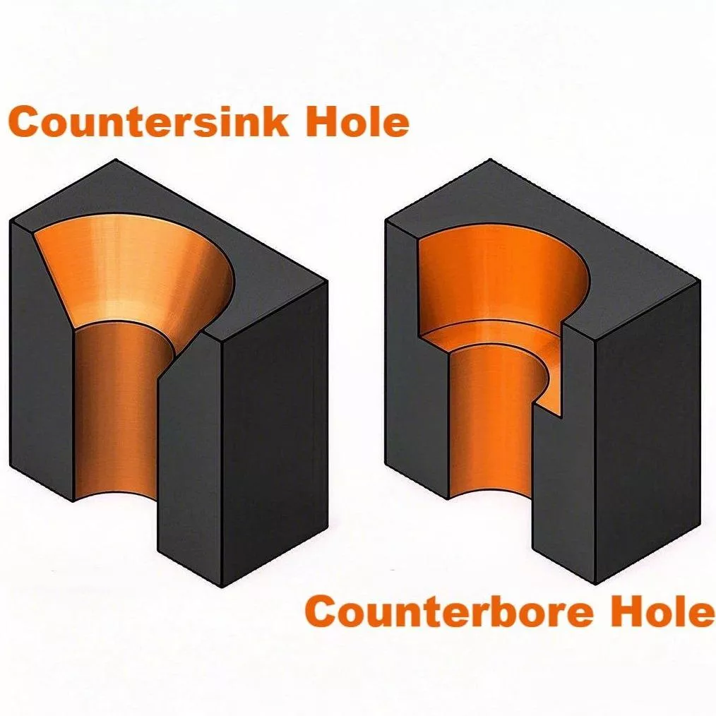
Countersinks and counterbores are both common hole features used to recess fastener heads below or flush with a part surface. Although they serve a similar purpose, their geometries and applications are different.
Understanding the difference between these two features helps engineers select the right design based on the fastener type, assembly requirements, and surface conditions.
| Feature | Countersink | Counterbore |
| Hole shape | Conical recess | Cylindrical recess with a flat bottom |
| Fastener type | Flat-head screws | Socket head cap screws and bolts |
| Bottom surface | Angled | Flat |
| Main purpose | Allows the screw head to sit flush with the surface | Allows the fastener head to sit below the surface |
| Common applications | Aerospace panels, sheet metal parts, precision assemblies | Machine components, fixtures, structural assemblies |
Countersink Holes
A countersink creates a tapered opening that matches the angled head of a flat-head screw. When installed, the screw head follows the conical surface and sits flush with the surrounding material.
Countersink holes are often selected when:
- A smooth external surface is required
- Clearance between components is limited
- Fastener appearance is important
- Aerodynamic or low-profile designs are needed
Counterbore Holes
A counterbore creates a larger cylindrical recess with a flat bottom, providing space for fasteners with cylindrical heads, such as socket head cap screws.
Counterbore holes are commonly used when:
- Higher clamping force is required
- A stronger fastening connection is needed
- The fastener head needs to be completely recessed
How to Choose Between Countersink and Counterbore
The choice depends mainly on the fastener design and functional requirements of the part.
Choose a countersink when:
- Using flat-head screws
- A flush surface is required
- Minimal surface interference is important
Choose a counterbore when:
- Using socket head screws or bolts
- A flat-bottom recess is preferred
- Greater fastening strength is required
For manufactured parts, both features should be clearly specified on engineering drawings, including hole size, depth, angle (for countersinks), and fastener requirements to ensure accurate production and assembly.
Hole Spacing Design Guidelines
Proper hole spacing is an important part of part design because the distance between holes and the distance between holes and part edges can directly affect structural strength, machining stability, and assembly performance.
When multiple holes are placed too close together or too close to an edge, the remaining material between features becomes weaker and may cause deformation, cracking, or difficulties during manufacturing. Therefore, engineers need to consider hole diameter, material thickness, loading conditions, and manufacturing processes when determining hole locations.
Distance Between Two Holes
The distance between adjacent holes should provide enough material between the openings to maintain part strength and ensure reliable manufacturing.
Insufficient spacing between holes can lead to:
- Reduced material strength
- Deformation during machining or forming
- Overlapping hole features
- Difficulty achieving accurate dimensions
When designing hole patterns, engineers should consider:
- Hole diameter
- Material properties
- Part thickness
- Required structural performance
For precision-manufactured components, maintaining adequate spacing also helps improve tool access and inspection capability.
Distance Between Hole and Part Edge
The distance between a hole and the edge of a part is another important design consideration. A hole positioned too close to an edge can weaken the surrounding material and increase the risk of cracking or distortion.
Common issues caused by insufficient edge distance include:
- Reduced load-bearing capability
- Edge deformation during machining or fabrication
- Difficulty maintaining dimensional accuracy
The required edge distance depends on several factors, including:
- Hole diameter
- Material strength
- Applied loads
- Manufacturing method
For example, thin sheet metal parts may require greater consideration of edge distance because the remaining material around the hole has less support.
Spacing Considerations for Multiple Countersink Holes
When multiple countersink holes are used on the same surface, the spacing between them must also account for the enlarged recessed areas created by the countersinks.
If countersinks are placed too close together, they may:
- Overlap with each other
- Reduce the strength of the surface area
- Create uneven seating conditions for fasteners
Proper spacing ensures that each fastener has sufficient support while maintaining the required surface integrity of the part.
Hole Spacing and Manufacturing Requirements
From a manufacturing perspective, hole spacing is not only a structural concern but also affects process reliability.
During machining or fabrication, sufficient spacing helps:
- Maintain tool accessibility
- Reduce material deformation
- Improve dimensional consistency
- Simplify inspection
By considering hole spacing during the design stage, engineers can create parts that are both functional and easier to manufacture.
How to Specify Hole Features on Engineering Drawings
Clear and complete hole specifications are essential for ensuring that designed features can be manufactured and inspected correctly. Whether a part includes standard holes, countersinks, counterbores, or threaded holes, engineering drawings should provide enough information to define the required geometry and functional requirements.
Incomplete hole callouts may lead to incorrect tool selection, assembly issues, or inconsistent production results. Proper documentation helps manufacturers understand the exact requirements before machining or fabrication begins.
Specify Hole Size and Type
The hole diameter and feature type should be clearly identified on the drawing.
Common examples include:
- Through holes
- Blind holes
- Threaded holes
- Clearance holes
- Countersink holes
- Counterbore holes
For countersink features, the drawing should specify:
- Pilot hole diameter
- Countersink diameter
- Countersink angle
- Required depth or surface condition
Define Hole Location and Position Tolerance
The location of holes is critical for parts that require accurate assembly with other components.
Engineering drawings should include:
- Hole center locations
- Reference datums
- Position tolerances when necessary
Proper positional control ensures that multiple components align correctly during assembly and prevents issues caused by misplaced holes.
Include Fastener Specifications
Since countersink dimensions depend on the fastener being used, designers should define the related screw or bolt requirements.
Important information may include:
- Screw size
- Thread specification
- Fastener standard
- Head style
- Required seating condition
Matching the hole feature with the correct fastener ensures proper engagement and prevents issues such as loose connections or improper seating.
Consider Manufacturing and Inspection Requirements
Hole features should be designed with manufacturing capabilities and inspection methods in mind.
For precision parts, manufacturers may need to verify:
- Hole diameter accuracy
- Hole position
- Countersink angle
- Countersink depth
- Surface condition
Clear drawing requirements allow manufacturers to select suitable processes, tooling, and inspection methods while maintaining consistent part quality.
For CNC machined components and other precision-manufactured parts, well-defined hole callouts help bridge the gap between design intent and final production results.
Common Hole Design Mistakes and How to Avoid Them
Proper hole design requires balancing functional requirements with manufacturing considerations. Many issues in assembly and production can be traced back to incorrect hole specifications, insufficient spacing, or a lack of consideration for the manufacturing process.
By identifying common design mistakes early, engineers can improve part reliability, reduce production difficulties, and avoid unnecessary modifications.
Using the Wrong Countersink Angle
One of the most common mistakes is selecting a countersink angle that does not match the fastener head.
An incorrect angle can cause:
- Poor contact between the screw and countersink surface
- Uneven load distribution
- Improper seating of the fastener
- Visible gaps or protrusion after assembly
How to avoid it:
Always select the countersink angle based on the actual fastener specification and clearly define the required angle on engineering drawings.
Making Countersinks Too Deep
Although a deeper countersink allows the fastener to sit further below the surface, removing too much material can weaken the surrounding area.
Potential issues include:
- Reduced material thickness
- Lower structural strength
- Damage to thin-wall components
How to avoid it:
Consider the part thickness, fastener head height, and required flush condition when determining countersink depth.
Placing Holes Too Close to Edges
Holes located too close to part edges leave insufficient material around the opening, which can reduce strength and create manufacturing challenges.
Possible problems include:
- Edge cracking
- Material deformation
- Reduced load capacity
- Difficulty maintaining accuracy
How to avoid it:
Maintain adequate edge distance based on hole size, material properties, and application requirements.
Insufficient Spacing Between Holes
When multiple holes are placed too close together, the remaining material between them may become weak or difficult to process.
Common issues include:
- Overlapping hole features
- Reduced surface strength
- Increased risk of deformation
How to avoid it:
Evaluate hole spacing together with material thickness, hole diameter, and functional requirements before finalizing the design.
Ignoring Manufacturing Limitations
A design that looks acceptable in CAD may still create challenges during production. Factors such as tool access, material behavior, and inspection requirements can affect the final result.
How to avoid it:
Consider manufacturing requirements during the design stage, including:
- Available tooling
- Machining or fabrication process
- Required tolerances
- Inspection methods
A design that accounts for manufacturing constraints helps create parts that are easier to produce, more consistent, and less likely to require redesign.
How Are Countersink Holes Made?
Countersink holes can be created using different methods depending on the material, production volume, and required accuracy. The right process helps ensure that the fastener sits properly while maintaining the strength and quality of the part.
Manual Countersinking
For simple projects or low-volume applications, countersink holes can be created using manual tools such as countersink bits attached to a drill.
This method is commonly used for softer materials, including:
- Wood
- Plastic
- Thin materials
Manual countersinking is cost-effective for small quantities but may have limitations in terms of dimensional accuracy and repeatability compared with automated processes.
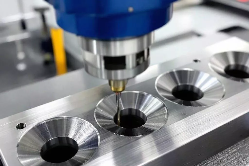
CNC Countersink Machining
For precision components and production parts, CNC machining provides better consistency and dimensional control.
During CNC countersinking, the machine follows programmed tool paths to create accurate countersink angles, diameters, and depths across multiple parts.
CNC countersink machining is commonly used for:
- Aluminum components
- Stainless steel parts
- Aerospace structures
- Precision mechanical assemblies
This process is especially suitable when tight tolerances and repeatable results are required.
Sheet Metal Countersinking
Countersink holes are widely used in sheet metal fabrication to allow screws and rivets to sit flush with thin metal surfaces.
When designing countersinks in sheet metal parts, engineers need to consider:
- Material thickness
- Remaining strength around the hole
- Fastener selection
Materials such as aluminum and steel sheets commonly use countersunk fasteners for applications requiring smooth surfaces and reliable assembly.
Combination Drills and Countersink Tools
Combination drill and countersink tools can create the pilot hole and countersink feature in a single operation.
This method improves efficiency by reducing machining steps and is often used for softer materials or less demanding applications.
However, for precision parts requiring strict dimensional control, dedicated machining processes are usually preferred.
Countersink Hole Design Best Practices
Proper planning during the design stage helps ensure that countersink holes meet assembly requirements and remain practical for manufacturing. The following practices can help create reliable countersink features.
- Define key dimensions: Specify the countersink diameter, angle, depth, and pilot hole size. Common countersink angles include 82° and 90°, which should match the selected fastener head design.
- Consider material thickness: Avoid excessive countersink depth, especially in thin materials, as it may weaken the part or cause deformation.
- Specify tolerances: Clearly define countersink dimensions and positional requirements on engineering drawings to ensure proper fastener installation and consistent production.
- Evaluate load requirements: Consider the forces applied to the fastener and ensure the countersink design provides sufficient material strength.
- Follow industry standards: Use standards such as ISO, ANSI, or DIN to ensure compatibility between countersink features and fasteners.
By following these guidelines, engineers can create countersink designs that improve assembly reliability, maintain part strength, and support efficient manufacturing.
CNC Machining Support for Precision Hole Features
Designing accurate hole features requires not only proper specifications but also reliable manufacturing processes. During production, factors such as material selection, tooling, machining strategy, and inspection methods can affect final hole accuracy and assembly performance.
Xtproto provides precision CNC machining solutions for components with complex hole features, including drilled holes, tapped holes, countersinks, and counterbores. With multi-axis machining capabilities and strict quality control processes, we help transform detailed engineering designs into accurate and manufacturable parts.
By considering design requirements and manufacturing limitations together, engineers can achieve better part performance, consistent quality, and smoother production workflows.