
What is GD&T and How is it Used?
In precision manufacturing, producing a part that matches its designed dimensions is not always enough. A component may meet basic size requirements but still fail to assemble or perform correctly due to issues with shape, alignment, or feature location.
Geometric Dimensioning and Tolerancing (GD&T) is a standardized engineering language used to define these critical geometric requirements. By applying symbols, tolerances, and datum references on technical drawings, GD&T helps designers, manufacturers, and inspectors clearly communicate how a part should be produced and measured.
From aerospace and automotive components to medical devices and precision CNC machined parts, GD&T plays an important role in improving manufacturing accuracy, ensuring assembly performance, and controlling production costs. This article explains what GD&T is, its key concepts, common symbols, and how it is applied in modern manufacturing.
What Is GD&T?
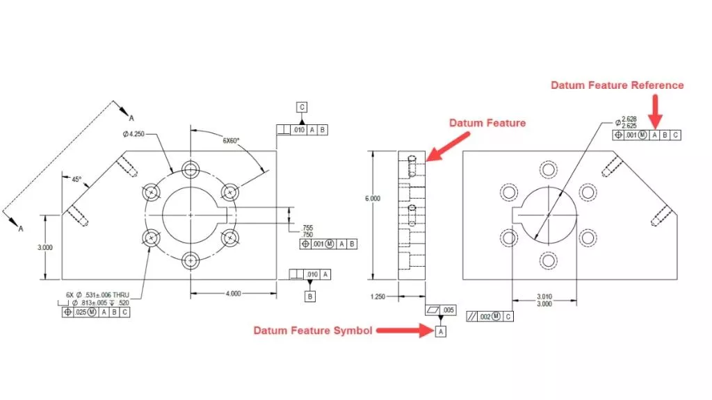
GD&T (Geometric Dimensioning and Tolerancing) is a standardized system used on engineering drawings to define the allowable variation of a part’s geometry. It uses specific symbols, tolerance values, and datum references to communicate design intent and describe how a component should be manufactured and inspected.
Unlike traditional dimensional tolerances that mainly control the size of a feature, GD&T defines the functional relationship between different features of a part. It allows engineers to specify not only how large a feature should be, but also how accurately it should be positioned, oriented, and shaped to ensure proper assembly and performance.
For example, a traditional tolerance may define a hole diameter as Ø10 ±0.05 mm, but it does not indicate whether the hole is located correctly relative to other features. GD&T can control additional requirements such as the hole’s position, perpendicularity, and relationship to established datum references.
The Purpose of GD&T
The main purpose of GD&T is to define the functional requirements of a part and provide a standardized way to communicate design intent throughout the manufacturing process.
The key purposes of GD&T include:
- Define Functional Requirements: GD&T describes how features should relate to each other to ensure proper assembly and performance.
- Communicate Design Intent: GD&T allows engineers to clearly define critical geometric relationships through standardized symbols and references.
- Control Geometric Variation: GD&T specifies acceptable limits for shape, orientation, and location beyond traditional dimensional tolerances.
How Is GD&T Used?
GD&T is used to define how a part should be manufactured, assembled, and inspected by controlling the geometric relationships between features. Unlike traditional dimensional tolerances that only specify size limits, GD&T communicates the designer’s functional requirements through standardized symbols and tolerance zones.
When creating engineering drawings, designers apply GD&T requirements to critical features such as holes, surfaces, and complex contours. These requirements define not only the allowable size variation but also the acceptable limits for feature location, orientation, and shape.
For example, a hole may meet its specified diameter tolerance but still cause assembly problems if its position is incorrect. GD&T solves this issue by adding controls such as position tolerance and datum references to define the exact relationship between features.
During manufacturing, GD&T requirements guide process planning by helping manufacturers determine suitable machining methods, fixture setups, and inspection strategies. Features with strict geometric requirements may require more precise machining processes or additional quality verification.
During inspection, GD&T provides measurable criteria for evaluating whether a finished part meets design specifications. Measurement equipment such as CMMs, gauges, and 3D scanning systems can verify characteristics including flatness, position, alignment, and profile accuracy.
By applying GD&T throughout design, manufacturing, and inspection, engineers can ensure that parts meet functional requirements while avoiding unnecessary manufacturing costs caused by excessive tolerances.
History of GD&T
The development of GD&T was driven by the need for more accurate and reliable manufacturing methods. In traditional engineering drawings, dimensional tolerances alone could not fully describe how parts should fit and function, which sometimes resulted in acceptable parts being rejected or incorrect parts being accepted.
During World War II, British engineer Stanley Parker identified this limitation while working at the Royal Torpedo Factory in Scotland. He introduced the concept of defining tolerances based on part function rather than only dimensional variation. His work helped establish the foundation of modern GD&T, including the concept of true position.
As precision manufacturing continued to develop, GD&T gradually became standardized. The U.S. military introduced early GD&T standards in the 1940s, followed by the ASME Y14.5 standard in 1957. Today, GD&T is widely used worldwide through standards such as ASME Y14.5 and ISO GPS, providing a common language for design, manufacturing, and inspection.
Basic Concepts of GD&T
GD&T is based on several fundamental concepts that define how part features are located, controlled, and inspected. These concepts provide the foundation for applying geometric tolerances on engineering drawings.
Datums
A datum is a theoretically exact reference point, axis, or plane used to establish a coordinate system for manufacturing and inspection. It provides a common reference for defining the location, orientation, and relationship between different features of a part.
For example, a machined housing may use its mounting surface as a primary datum, while other surfaces or holes are controlled relative to this reference.
Features
In GD&T, a feature refers to a specific physical element of a part that requires control. Features can include:
- Surfaces
- Holes
- Slots
- Cylinders
- Axes
Each feature can have different geometric requirements depending on its function.
Feature Control Frames
A feature control frame is a rectangular box used on engineering drawings to specify GD&T requirements. It communicates:
- The geometric characteristic being controlled
- The tolerance value
- Applicable modifiers
- Datum references
This allows manufacturers and inspectors to clearly understand how a feature should be produced and measured.
Tolerance Zones
GD&T defines acceptable variation through tolerance zones rather than only numerical limits. The shape of the tolerance zone depends on the type of geometric control being applied.
For example:
- Flatness uses two parallel planes as the tolerance zone.
- Position uses a cylindrical tolerance zone to control feature location.
Material Condition Modifiers
Material condition modifiers define how feature size affects geometric tolerance requirements.
Common modifiers include:
- MMC (Maximum Material Condition): The condition where a feature contains the maximum amount of material.
- LMC (Least Material Condition): The condition where a feature contains the minimum amount of material.
- RFS (Regardless of Feature Size): The tolerance applies independently of feature size.
GD&T Symbols and Their Meanings
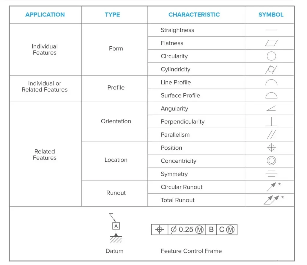
GD&T uses standardized symbols to define the allowable variation of part features on engineering drawings. These symbols are grouped into different categories based on the type of geometric characteristic they control, including form, profile, orientation, location, and runout.
Understanding these symbols helps engineers, manufacturers, and inspectors accurately interpret design requirements and ensure that parts meet their functional requirements.
Form Tolerances
Form tolerances control the shape of individual features without referencing a datum. They define how much a feature can deviate from its ideal geometric form.
Common form tolerances include:
- Straightness — Controls how much a line element or axis can deviate from a perfect straight line.
- Flatness — Controls how much a surface can vary from a perfectly flat plane.
- Circularity — Controls the roundness of circular features.
- Cylindricity — Controls the overall accuracy of a cylindrical surface, including variations in roundness, straightness, and taper.
Profile Tolerances
Profile tolerances control the shape of complex surfaces and contours. They are commonly used for parts with curved or irregular geometries.
Common profile controls include:
- Profile of a Line — Controls the variation of a two-dimensional cross-sectional shape.
- Profile of a Surface — Controls the variation of a three-dimensional surface.
Profile tolerances are widely used in aerospace components, molds, and complex CNC machined parts where accurate surface geometry is required.
Orientation Tolerances
Orientation tolerances control the angular relationship between features and reference datums.
Common orientation tolerances include:
- Parallelism — Controls whether a surface or feature remains parallel to a datum.
- Perpendicularity — Controls whether a feature maintains a 90-degree relationship with a datum.
- Angularity — Controls a feature at a specified angle relative to a datum.
These controls are important for ensuring proper alignment and assembly between components.
Location Tolerances
Location tolerances define the position of features relative to other features or datums.
Common location tolerances include:
- Position — Controls the exact location of features such as holes, slots, and mounting points. It is one of the most commonly used GD&T controls in CNC machining.
- Concentricity — Controls the alignment of cylindrical features relative to a common axis.
- Symmetry — Controls the balanced relationship between corresponding features around a center plane.
Runout Tolerances
Runout tolerances are mainly used for rotating components and control surface variation during rotation around a datum axis.
Common runout controls include:
- Circular Runout — Controls variation at individual circular cross-sections during rotation.
- Total Runout — Controls the variation of an entire surface while the part rotates around its datum axis.
Runout requirements are commonly applied to shafts, bearings, and other precision rotating components.
Size and Location Control in GD&T
Although geometric symbols define the shape and relationship of features, GD&T also works together with dimensional requirements to control feature size and position.
For example:
- Size defines the physical dimensions of a feature, such as hole diameter or shaft diameter.
- Position defines where that feature is located relative to established datums.
- Orientation defines how the feature is aligned.
- Form defines the accuracy of the feature’s shape.
Together, these controls provide a complete description of how a part should be manufactured and inspected.
GD&T Symbols Reference Chart
Advantages of Using GD&T
GD&T provides several advantages in precision manufacturing by improving communication, reducing errors, and ensuring that components meet their functional requirements.
- Improve Design Communication: GD&T provides a standardized language for designers, manufacturers, and inspectors.
- Ensure Better Part Performance: GD&T controls feature relationships to improve assembly accuracy and component reliability.
- Reduce Manufacturing Costs: GD&T prevents unnecessary tight tolerances and allows manufacturers to focus precision where it is needed.
- Improve Quality Inspection: GD&T provides clear measurement requirements for verifying part accuracy.
GD&T and 3D Measurement
GD&T and 3D measurement work together to ensure that manufactured parts meet their specified geometric requirements. GD&T defines the acceptable variation of a feature, while 3D measurement verifies whether the actual part meets those requirements.
GD&T Inspection with 3D Measurement
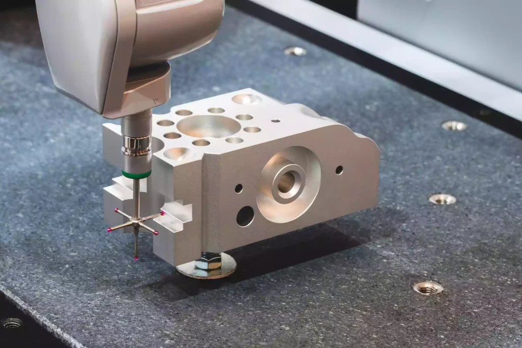
During inspection, measurement data is collected from physical parts using methods such as contact probing, CMM (Coordinate Measuring Machine), or 3D scanning. The collected data can then be compared with CAD models and GD&T specifications to evaluate part accuracy.
Common GD&T Features Measured
3D measurement systems can evaluate various geometric characteristics, including:
- Flatness — Checks whether a surface remains within the specified tolerance zone.
- Straightness — Measures the deviation of lines or axes from the ideal condition.
- Position — Verifies the location accuracy of holes and other features.
- Perpendicularity and Parallelism — Ensures proper alignment between features.
- Profile — Measures complex surfaces and contours.
Role of CMM and 3D Scanning
CMMs are commonly used for high-precision GD&T inspection, especially for critical dimensions and geometric requirements. 3D scanning provides full surface data and is useful for inspecting complex geometries, comparing parts with CAD models, and identifying deviations.
By combining GD&T requirements with advanced measurement technologies, manufacturers can verify part quality and maintain consistent production accuracy.
How GD&T Supports CNC Machining Processes
GD&T plays an important role throughout the CNC machining process by connecting design requirements with manufacturing and inspection activities. It helps manufacturers understand which features are critical and how they should be produced and verified.
Design and Drawing Review
Before machining begins, engineers review drawings with GD&T requirements to identify critical features, datum references, and required tolerances. This helps determine suitable machining strategies and inspection methods.
Machining Process Planning
GD&T requirements influence decisions such as:
- Machine selection
- Fixture design
- Machining sequence
- Tool selection
For example, parts with strict position or profile requirements may require multi-axis machining or more precise setups.
Inspection and Verification
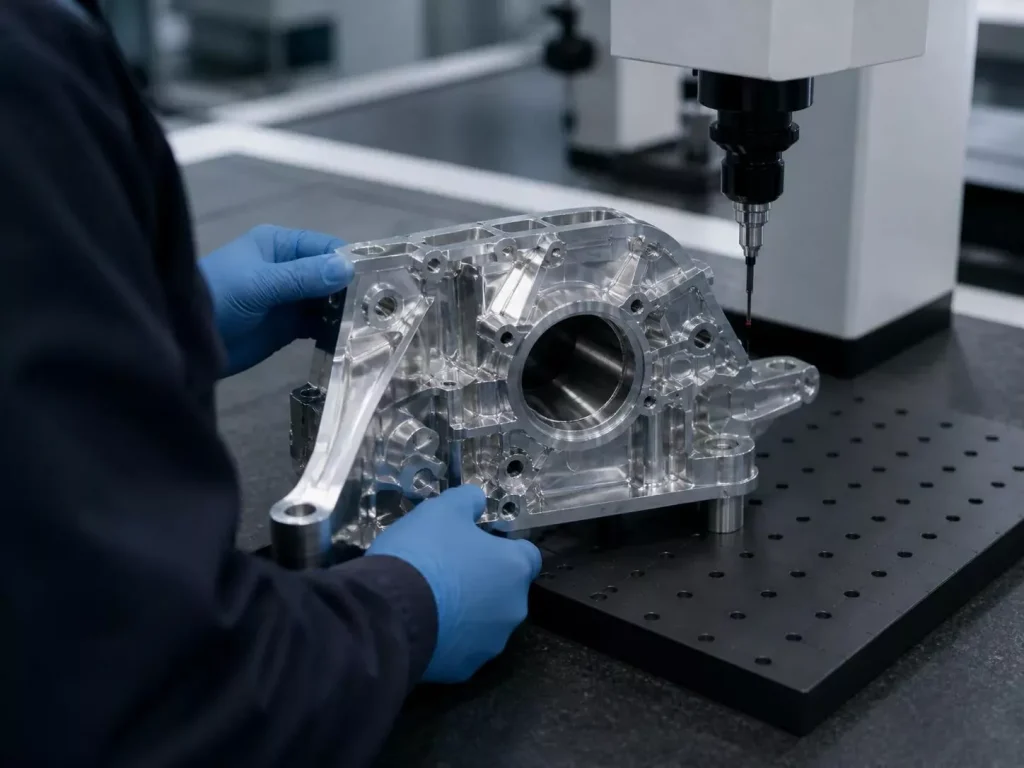
After machining, manufacturers use measurement equipment such as CMMs and precision gauges to verify whether the finished part meets GD&T specifications.
By applying GD&T throughout CNC machining, manufacturers can achieve better consistency, reliable assembly performance, and improved part quality.
Applications of GD&T
GD&T is widely used in industries where part accuracy, assembly performance, and reliability are critical. By defining precise geometric requirements, GD&T helps manufacturers produce components that meet strict functional requirements.
Aerospace Industry
Aerospace components often require high precision due to strict safety and performance requirements. GD&T helps control complex geometries, alignment, and assembly features in aircraft and aerospace systems.
Automotive Industry
In automotive manufacturing, GD&T helps ensure interchangeability and consistent assembly of high-volume components. It is commonly applied to engine parts, transmission components, and precision mechanical assemblies.
Medical Industry
Medical devices and implants require accurate dimensions and reliable performance. GD&T helps control critical features and ensures components meet functional and quality requirements.
Industrial Equipment
Industrial machinery often contains components that must operate together under demanding conditions. GD&T helps maintain proper alignment, fit, and long-term reliability of mechanical parts.
Common GD&T Mistakes
Although GD&T provides a clear method for defining part requirements, incorrect application can lead to unnecessary costs or manufacturing issues.
Overusing Tight Tolerances
Applying strict tolerances to non-critical features can increase machining difficulty and production costs without improving part performance.
Incorrect Datum Selection
Poor datum choices can create unclear measurement requirements and affect the accuracy of manufacturing and inspection.
Ignoring Manufacturing Limitations
GD&T requirements should consider actual machining capabilities and inspection methods to ensure they are practical and achievable.
Lack of Communication
Designers, manufacturers, and inspectors should have a consistent understanding of GD&T requirements to avoid interpretation errors.
How Xtproto Supports GD&T Requirements
At Xtproto, we support customers with precision CNC machining projects that require GD&T specifications. Our engineering team reviews technical drawings and geometric requirements to understand critical features, datum references, and inspection expectations before production begins.
By combining advanced CNC machining capabilities with precision inspection processes, we can manufacture components with accurate feature locations, controlled geometry, and consistent quality. GD&T requirements are integrated throughout the machining and verification process to help ensure that finished parts meet functional requirements and assembly expectations.
Whether for complex prototypes or production components, Xtproto provides reliable machining solutions for customers requiring precise geometric control and high-quality manufactured parts.
Conclusion
GD&T provides a standardized way to define, manufacture, and inspect precision components by controlling not only dimensions but also the geometric relationships between features. It helps designers communicate functional requirements, enables manufacturers to achieve consistent results, and improves quality control throughout the production process.
As precision manufacturing continues to advance, GD&T remains an essential tool for industries requiring accurate and reliable components. At Xtproto, we apply GD&T requirements together with advanced CNC machining and inspection capabilities to deliver high-quality custom parts that meet complex design specifications.