
Can STL Files Be Used for CNC Machining?
When preparing parts for CNC machining, choosing the appropriate 3D model format is crucial for ensuring machining accuracy, efficient programming, and consistent product quality. However, many customers familiar with 3D printing workflows often provide STL files and assume these can be directly used for CNC machining.
STL files are widely used in additive manufacturing because they represent the external shape of parts using a mesh of triangular faces. However, CNC machining requires more detailed and precise design information, including accurate dimensions, tolerances, feature definitions, and editable geometry. Since STL files do not contain this manufacturing data, they are generally unsuitable as the primary input format for CNC programming.
This article will explain why STL files cannot be directly used for CNC machining, the limitations of STL models in precision manufacturing, and which file formats are recommended for better machining results.
What is an STL file?
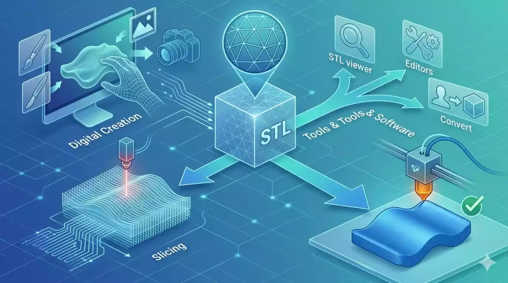
STL (Stereolithography) is a 3D model file format originally developed for additive manufacturing and is one of the most commonly used formats in 3D printing workflows. Unlike CAD files, which store complete design information, STL files describe the outer surfaces of a part through a set of connected triangular faces (also known as a mesh).
Because STL files only define the external geometry of the model, they are suitable for applications where the primary requirement is to reproduce the shape of an object, such as 3D printing, rapid prototyping, and 3D scanning. The file does not contain information about part design features, manufacturing history, dimensions, or engineering requirements.
For example, an STL file can show the shape and location of holes on a part, but it does not define critical details such as precise hole diameters, thread specifications, dimensional tolerances, or surface finish requirements. This limitation makes STL files insufficient for precision manufacturing processes such as CNC machining, where accurate design data is crucial for toolpath programming and quality control.
Unlike additive manufacturing, CNC machining removes material from a workpiece based on precisely defined geometry. Therefore, mechanics typically need CAD-based file formats that include complete solid model information rather than just surface representations.
Can STL files be used for CNC machining?
Yes, in some cases, STL files can be used for CNC machining, but for most precision machining applications, it is not the preferred file format. The suitability of an STL file depends on the complexity of the part, the required precision, and the type of machining operation.
STL files are primarily used to describe the external shape of a part using a triangular mesh. This makes them suitable for CNC machining processes focused on reproducing complex surface geometries, such as 3D contour machining, surface part machining, and machining of parts generated from 3D scan data.
For example, when machining parts with complex freeform surfaces, CAM systems can import STL files and generate toolpaths based on the mesh geometry. In these cases, accurate design history or parametric features may not be required, making STL files a viable option.
However, for precision CNC machining parts requiring tight tolerances, thread features, precise hole diameters, or complex engineering specifications, the use of STL files is generally not recommended. Because STL files do not contain dimensional information, feature definitions, or manufacturing requirements, additional CAD reconstruction may be required before machining.
Therefore, while STL files can be used for specific CNC workflows, CAD-based formats such as STEP, IGES, and native CAD files remain the preferred choice for producing accurate and reliable CNC machined parts.
Why STL Files Are Not Ideal for Precision CNC Machining
Although STL files can be used for certain CNC applications, they are not the preferred format for precision CNC machining. The main limitation is that STL files only contain surface mesh information, while CNC machining requires complete engineering data to define the part’s geometry, dimensions, and manufacturing requirements.
Unlike 3D printing, where the main goal is to reproduce the overall shape of a model layer by layer, CNC machining removes material from a solid workpiece based on accurate toolpaths. To generate reliable machining programs, manufacturers need more than just the external appearance of a part.
1. STL Files Do Not Contain Parametric Design Information
One of the biggest limitations of STL files is that they do not store parametric CAD information. An STL model is created by converting a solid CAD model into a mesh made of thousands of small triangular surfaces. Once converted, the original design features are no longer available.For CNC machining, engineers often need access to specific design features, including:
- Hole diameters and locations
- Thread specifications
- Pocket dimensions
- Wall thickness
- Chamfers and fillets
- Reference datums
For example, an STL file may show that a component has a circular hole, but it cannot define whether the hole should be:
- Drilled to a specific diameter
- Reamed for higher accuracy
- Threaded for an assembly connection
- Machined with a specific tolerance requirement
Without this information, CNC programmers cannot accurately determine machining operations or select the correct tools. Additional CAD modeling or engineering drawings are usually required before production.
2. STL Files Do Not Define Critical Dimensions and Tolerances
Precision CNC machining relies heavily on dimensional accuracy and tolerance control. A manufacturing drawing or CAD model can specify exactly how a part should be produced, including critical dimensions and acceptable variations.However, STL files only represent the approximate surface shape of a component. They do not contain information about:
- Dimensional tolerances
- Geometric tolerances
- Surface finish requirements
- Critical mating surfaces
For example, two parts may look identical in an STL model, but one application may require a standard hole tolerance while another may require a precision fit between assembled components.Since STL files cannot identify these functional requirements, using them alone increases the risk of producing a part that matches the shape but fails during assembly or operation.
3. STL Mesh Geometry Can Affect Machining Accuracy
STL files represent geometry through a collection of triangular faces rather than true mathematical surfaces. The accuracy of the model depends on the mesh resolution used during export.
A low-resolution STL file may create problems such as:
- Faceted curved surfaces
- Reduced edge accuracy
- Loss of small features
- Incorrect surface representation
For simple shapes, these differences may be minor. However, for precision CNC machining, especially when manufacturing components with complex curves or tight tolerances, even small deviations can affect final part quality.Higher-resolution STL files can improve the appearance of the mesh, but they still do not provide the editable solid geometry available in CAD formats.
4. STL Files Are Difficult to Modify for CNC Requirements
During CNC manufacturing, engineers often need to adjust part designs based on machining requirements. These changes may include:
- Adding machining allowances
- Modifying tool access areas
- Adjusting hole sizes
- Changing wall thickness
- Optimizing features for manufacturability
Because STL files are mesh-based, making these modifications is difficult and often requires rebuilding the model in CAD software.A solid CAD file allows engineers to directly edit features while maintaining accurate dimensions, making it much more suitable for CNC programming and production.
Recommended File Formats for CNC Machining
For precision CNC machining, CAD-based file formats are preferred because they contain accurate geometric data and provide the information required for programming, inspection, and manufacturing. Unlike STL files, which only represent surface mesh geometry, CAD files preserve the actual design structure of a part, making them more reliable for producing high-quality machined components.
The most commonly recommended file formats for CNC machining include STEP, IGES, and native CAD files.
1. STEP Files (.step / .stp)
STEP (Standard for the Exchange of Product Model Data) is one of the most widely used file formats for CNC machining. It allows different CAD software platforms to exchange accurate 3D solid models while maintaining essential geometric information.
Advantages of STEP files include:
- Maintains solid geometry rather than mesh surfaces
- Preserves accurate dimensions and complex features
- Compatible with most CAD/CAM software
- Suitable for CNC milling, CNC turning, and multi-axis machining
Because STEP files provide reliable and editable 3D data, they are commonly preferred for production CNC machining. Customers providing STEP files can help manufacturers reduce programming time and minimize the risk of geometry errors.
2. IGES Files (.igs / .iges)
IGES (Initial Graphics Exchange Specification) is another commonly used CAD exchange format. It was developed to improve compatibility between different CAD systems and is especially useful for transferring surface geometry.
IGES files can be used for:
- Complex surface models
- Legacy CAD data exchange
- Components requiring detailed surface information
However, compared with STEP files, IGES may have limitations when handling complex solid models because it was originally designed primarily for surface data exchange. For most modern CNC machining applications, STEP is generally preferred.
3. Native CAD Files
Native CAD files are the original files created in specific CAD software, such as:
- SolidWorks (.sldprt)
- Autodesk Inventor (.ipt)
- Creo (.prt)
- Fusion 360 design files
These files contain the complete design history, including:
- Feature operations
- Sketches
- Dimensions
- Constraints
- Design parameters
Providing native CAD files allows engineers to better understand the original design intent and make necessary adjustments for manufacturability. This is especially helpful for complex parts that require design optimization before machining.
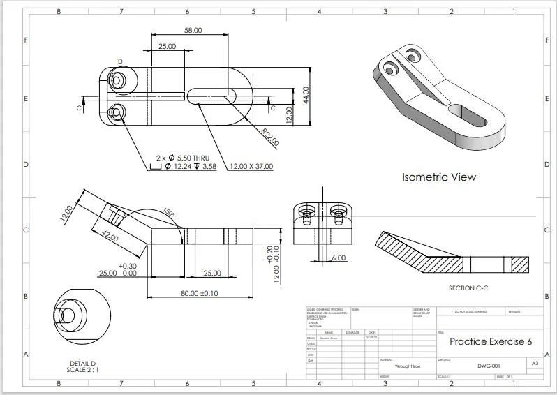
4. 2D Technical Drawings (Recommended for Precision Parts)
Although 3D CAD files define the overall geometry, technical drawings are often required for precision CNC machining.A detailed drawing can specify:
- Critical dimensions
- Tolerance requirements
- Surface finish specifications
- Thread requirements
- Material information
- Inspection criteria
For high-precision components, providing both a 3D CAD model and a 2D drawing ensures that the manufacturer understands not only the shape of the part but also the exact manufacturing requirements.For most CNC machining projects, the recommended file package is:
STEP file + 2D technical drawing
This combination provides accurate 3D geometry along with the engineering specifications needed to manufacture parts with consistent quality and precision.
How to Prepare Files for CNC Machining
Providing the correct files is an important step in ensuring accurate CNC machining results. While a 3D model defines the shape and geometry of a part, manufacturers also need additional information to understand the material, precision requirements, and finishing expectations before production begins.A complete CNC machining file package helps engineers evaluate manufacturability, create accurate toolpaths, select suitable machining processes, and avoid delays caused by missing specifications.
1. Provide a 3D CAD Model
The primary file for CNC machining should be a CAD-based 3D model, preferably in formats such as:
- STEP (.step / .stp)
- IGES (.igs / .iges)
- Native CAD files
The 3D model provides the basic geometry of the component, including:
- Overall dimensions
- Complex features
- Internal structures
- Machining areas
For most precision CNC projects, a STEP file is recommended because it maintains accurate solid geometry and is widely supported by CAD/CAM software.
2. Include 2D Technical Drawings for Precision Requirements
For parts with tight tolerances or functional requirements, a 2D drawing should be provided together with the 3D model.
Technical drawings communicate details that may not be fully defined in a 3D file, including:
- Critical dimensions
- Dimensional tolerances
- Geometric tolerances
- Thread specifications
- Surface finish requirements
- Inspection requirements
For example, a 3D model can show the location of a hole, while a technical drawing can specify that the hole requires a particular diameter, tolerance, and surface finish.
3. Specify Material Requirements
Material selection directly affects machining parameters, tool selection, and final part performance.
Customers should provide material information such as:
- Aluminum alloys (6061, 7075, etc.)
- Stainless steel grades (304, 316, 17-4 PH, etc.)
- Titanium alloys
- Engineering plastics
If the material is not specified, manufacturers may not be able to determine the appropriate machining strategy or verify whether the final part meets application requirements.
4. Define Surface Finish and Post-Processing Requirements
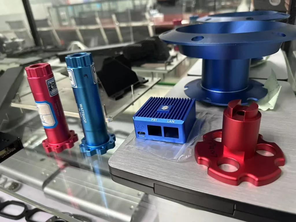
CNC machined parts often require additional finishing operations after machining. These requirements should be clearly stated before production.
Common requirements include:
- Anodizing
- Powder coating
- Plating
- Passivation
- Polishing
- Bead blasting
- Heat treatment
Specifying the required surface finish in advance helps manufacturers plan machining allowances and ensure the final dimensions remain within tolerance after finishing.
5. Provide Quantity and Production Requirements
The required production volume can influence the recommended manufacturing process.
Customers should provide:
- Prototype quantity
- Low-volume production requirements
- High-volume production quantities
- Expected delivery timeline
With complete project information, manufacturers can select the most efficient machining strategy and provide a more accurate quotation.
Xtproto’s CNC Machining File Requirements
At Xtproto, accurate file preparation is an essential part of delivering high-quality CNC machined parts. By reviewing complete design data before production, our engineering team can evaluate part geometry, optimize machining strategies, and ensure the final components meet the required specifications.
For CNC machining projects, Xtproto recommends customers provide CAD-based files rather than STL files whenever possible. Preferred file formats include:
- STEP (.step / .stp)
- IGES (.igs / .iges)
- Native CAD files
These formats provide accurate 3D geometry and allow engineers to properly prepare CNC programming, machining operations, and inspection plans. For parts requiring tight tolerances or functional assembly, customers should also provide 2D technical drawings. Drawings help define critical manufacturing requirements, including:
- Dimensional tolerances
- Geometric tolerances
- Thread specifications
- Surface finish requirements
- Material specifications
- Special inspection requirements
With complete design information, Xtproto’s engineering team can identify potential manufacturing challenges early, recommend suitable machining solutions, and improve production efficiency. Whether for rapid prototypes or production CNC machined parts, Xtproto supports a wide range of customer file formats and provides professional manufacturing guidance from design review to final production.
Conclusion
STL files can be used in certain CNC machining applications, especially for machining complex surface geometries, 3D scanned models, or parts that only require copying the external shape. However, STL files are not the first choice for precision CNC machining because they only contain mesh-based surface information and lack the necessary manufacturing data.
For CNC-machined parts requiring tight tolerances, accurate dimensions, thread features, and reliable production consistency, CAD-based file formats (such as STEP, IGES, and native CAD files) offer better results. These formats enable manufacturers to obtain accurate geometry, optimize toolpaths, and ensure that the final part meets engineering requirements.
Providing the correct file format is a crucial step in achieving efficient CNC machining and high-quality finished parts. Xtproto supports industry-standard CAD formats and collaborates with customers to review designs, optimize machining processes, and deliver precision CNC-machined parts for prototyping and mass production.